


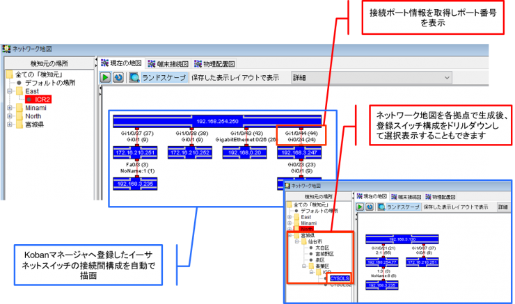
Connection Diagram Between Switches
- Display switch connection diagram for each location
- Port name configured within the switch
- Port number
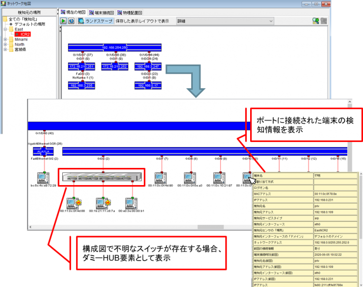
Switch Connection Terminal Diagram
The diagram shows the terminals connected to each switch port. Additionally, by positioning the cursor over the device icon, information about the selected device will be displayed.
If a non-intelligent switch that is not registered in NetSkateKoban Manager or does not support SNMP is detected, it will be displayed as an unknown switch.
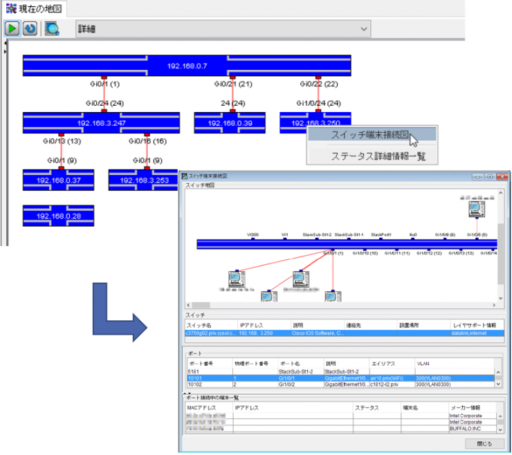
Connected Terminal Display for Each Switch
By selecting a switch displayed in the switch connection diagram, you can display information about the terminals connected to each port of that switch.
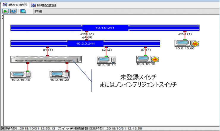
Detection and Illustration of Unregistered and Non-Intelligent Switches
If a switch that is not registered in NetSkateKoban Manager or a non-intelligent switch is detected, it will also be illustrated. It is possible to recognize switches that are not normally allowed or unknown, making it possible to prevent negative effects on the network due to the connection of unintended network devices such as unauthorized Wi-Fi routers.
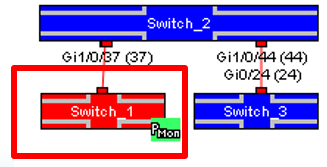
Alive Monitoring Using Ping
- You can monitor whether the Ethernet switch is alive or not by pinging it. If it is being monitored, PMon will appear in the diagram that represents the switch.
- Ping monitoring detects whether a ping is reachable by checking at set intervals. By setting the default settings for Ping alive monitoring in advance, it is possible to monitor multiple switches under the same monitoring conditions.
- You can set the action to notify the administrator by e-mail or by executing a command in the action settings when unreachable ping is detected.

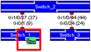
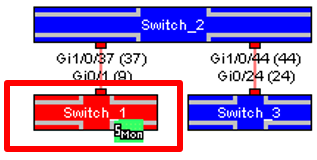
Threshold Monitoring Using SNMP
- Threshold monitoring of Ethernet switches can be performed by setting SNMPMon (threshold monitoring) as the SNMPMon target. The SNMPMon target holds a configurable management object (MO). Monitor these MOs and record the results. If it is being monitored, "SMon" will be displayed in the diagram showing the switch.
- By setting the SNMPMon default settings in advance, you can register multiple monitoring targets at once from the switch list with the same monitoring conditions.
- You can set an action to notify the administrator by email or command execution using the SNMPMon action.
Illustrated/Monitorable Switch Specifications
- SNMPv2-MIB (RFC3418)
- IF-MIB (RFC2863) (If not supported, a connection diagram can be drawn, but the IF name will not be displayed)
- IP-MIB (RFC4293) Q-BRIDGE-MIB (RFC4188) or BRIDGE MIB (RFC4363)
Configuration Information Required for SNMP Access
- IP Address
- SNMP Version
- Community Name
Verified Switch
- Catalyst 2960
- Catalyst 3560C
- Catalyst 3750X
- Catalyst 4948E
- FS926M
- ALAXALA AX2130
- ALAXALA AX2530
- EHB-SG2B08
- EHB-SG2B16
- BS-GS2008
- BS-GS2016
- Switch-M8eGPWR+
- Switch-M5eGPWR+
- Switch-M24eG (product number PN28240)
- Switch-M8eG (product number PN28080)
- S350 Series (product number GS308T)